The Following topics are the MAIN areas of study for this unit for both Foundation and higher level candidates. It is advised that these areas should be revised in more depth.
AREAS OF STUDY
b) Insulating Materials
can be charged by rubbing (negative charges move from one material to another)
c) Examples of Static (e.g. balloons sticking to a wall)
also
d) How Electroscopes work

Any charged material brought up to the top plate will repel the charges down into the leaves making them push apart
| COMPONENT | SYMBOL |
|---|---|
| Battery | |
| Cell | |
| Bulb | |
| Ammeter | |
| Voltmeter | |
| Resistor | |
| Joined Wire |
Rate of using Electrical Energy
| POWER | = | VOLTAGE | × | CURRENT |
| P | = | V | × | I |
| (watts) | (volts) | (amps) |

| VOLTAGE | = | CURRENT | × | RESISTANCE |
| V | = | I | × | R |
| (Volts) | (amps) | (ohms) |


| COMPONENT | SYMBOL | HOW IT WORKS | What it is used for |
|---|---|---|---|
| Light Dependant Resistor | Made from Cadmium Sulphide (light Sesisive material. It's resistance changes with the amount of light (more light = Less resistance) | Light Sensor | |
| Thermistor | Sensitive to heat. it's resistance changes with heat( more heat = Less Resistance | Temperature sensor | |
| Diode | Allows current to flow through it in ONE DIRECTION only | AC to DC rectification, component protection | |
| Capacitor | it stores Electrical charge | Timing, Smoothing ac, creating rf signal |
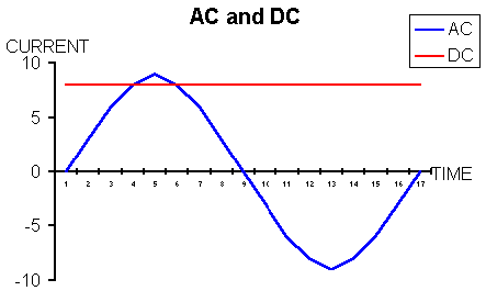
AC-Alternating current the sort of current you get from the mains (looks like sine wave)
DC Direct current- the sort you get from batteries (flat line)
